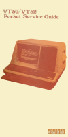
VT50/VT52 Pocket Service Guide

Company:Digital Equipment Corporation
Part:EK-VT502-PG-001
Date:1979-01
Keywords:terminal

Table of Contents

  • 1 Introduction
    • 1.1 Purpose
    • 1.2 Reference Documentation
  • 2 Troubleshooting
    • 2.1 Troubleshooting Philosophy
  • 3 Removal and Replacement
    • 3.1 Removing and Replacing the EIA or 20 mA Adapter Card
    • 3.2 Removing and Replacing the Power Supply/Monitor Assembly Heat Sink Panel
    • 3.3 Removing and Replacing the Base Assembly
    • 3.4 Removing and Replacing the Character Generator
    • 3.5 Removing and Replacing the Printer Interface Option
    • 3.6 Removing and Replacing the RUT and DP Modules
    • 3.7 Removing and Replacing the Anti-Static Ground Shield
    • 3.8 Removing and Replacing the Keyboard
    • 3.9 Removing and Replacing the Power Supply/Monitor Assembly
    • 3.10 Removing and Replacing the CRT Assembly
    • 3.11 Removing and Replacing the CRT Yoke
    • 3.12 Removing and Replacing the Electrolytic Copier Option
    • 3.13 Removing and Replacing the Transformer Assembly
  • 4 Alignment and Adjustments
    • 4.1 CRT Yoke Alignment
    • 4.2 Display Adjustments
  • 5 Acceptance Test Procedures
    • 5.1 General
    • 5.2 Terminal Tests
    • 5.3 Copier Option Tests
    • 5.4 Printer Interlace Option Tests
  • 6 Installation and Operation
    • 6.1 Installation
    • 6.2 Operation
  • 7 PMK04 Operation
  • A Care and Handling of Cathode Ray Tubes
  • B Replaceable Modules and Assemblies Parts List
  • C Physical/Functional Block Diagram

Copies

Address: http://vt100.net/dec/ek-vt502-pg-001.pdf
Site: Paul Williams' VT100.net
Format: PDF
Size: 2471322 bytes (2.4 MiB)
MD5: 70550c4b2a6c4453c60fde319ad2e125
Credits:Scanned by Antonio Carlini
Mirrors: